
Products
Products
Two products, one workflow. The T1 fills, stops and crimps glass cartridges; the dual-chamber cartridge is the container it handles.
01 — Filling machine
T1 All-Electric Filling Machine
One bench-top unit that fills, stops and crimps glass cartridges in small batches.
- Drive
- All-electric
- Operation
- Semi-automatic
- Container
- Glass cartridge
- Interface
- Touchscreen HMI
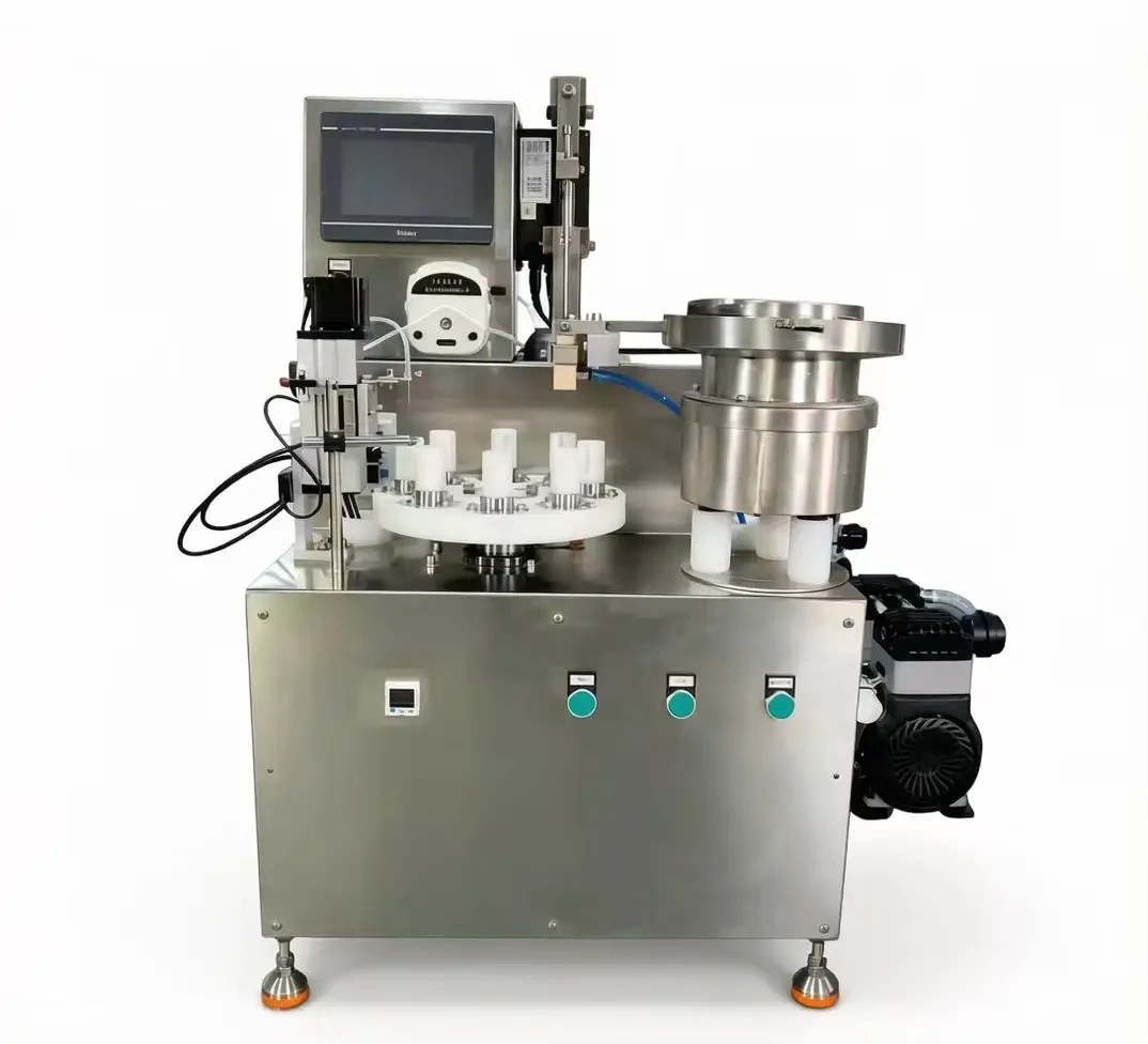
T1 as built: touchscreen, eight-position rotary table and stopper bowl.
Overview
Every motion on the T1 is driven electrically. There is no pneumatic circuit to install and no compressed-air supply to maintain; the machine runs from a single electrical supply and is operated from the touchscreen on the frame.
Work is arranged around a rotary table: filling at one position, stopper placement at the next, crimping after that. Stoppers are oriented in the bowl on the right and fed to the insertion head automatically.
Process
One cycle, six steps.
- 01
Manual loading
Empty glass cartridges are set into the nests of the rotary table by the operator. Batch size is decided at this point.
- 02
Automatic filling
The filling head dispenses product into each cartridge as the table indexes from station to station.
- 03
Stopper sorting
The vibratory bowl on the right of the frame aligns the stoppers and feeds them in one direction to the transfer point.
- 04
Stopper insertion
The insertion head lowers each stopper into the cartridge neck before the table moves on.
- 05
Crimping
The crimping station closes the aluminium cap over the cartridge flange, sealing the filled container.
- 06
Manual unloading
The operator lifts the finished cartridges from the table and passes them to the next process.
| Specification | Value |
|---|---|
| Drive type | All-electric |
| Operation | Semi-automatic, manual load and unload |
| Process stations | Filling, stopper sorting, stopper insertion, crimping |
| Container | Glass cartridge |
| Control | Touchscreen HMI |
| Construction | Stainless steel |
| Air supply | Not required |
| Output | On request |
| Filling accuracy | On request |
| Container size range | On request |
| Power supply | On request |
| Dimensions | On request |
| Weight | On request |
In operation
A full cycle, filmed.
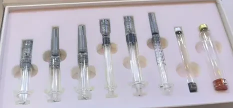
Dual-chamber cartridges, shown with caps in place.
02 — Container
Dual-Chamber Cartridge
Two chambers in one glass barrel, kept separate until the moment of use.
- Front chamber
- Holds the liquid or the reconstituted formulation.
- Rear chamber
- Holds the diluent or the lyophilised powder, depending on configuration.
- Mid seal
- Separates the two chambers until the plunger is advanced.
- Plunger
- Moved at the point of use so the two components combine in the front chamber.
- Aluminium cap
- Closes the neck after filling and is crimped in place.
| Configuration | Value |
|---|---|
| Chamber capacity | On request |
| Seal configuration | On request |
| Cap finish | On request |
Where it is used
Dual-chamber cartridges suit products that must stay apart until use — a lyophilised powder and its diluent, or two liquid components. One container carries both, keeping storage and preparation in a single format.
Pairing with the T1
Cartridge formats are filled, stopped and crimped on the T1 platform. Chamber configuration and the filling sequence are confirmed per project before the machine is built.